Choke Manifold
Description
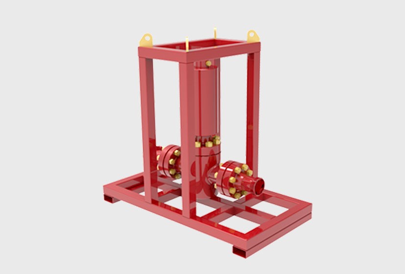
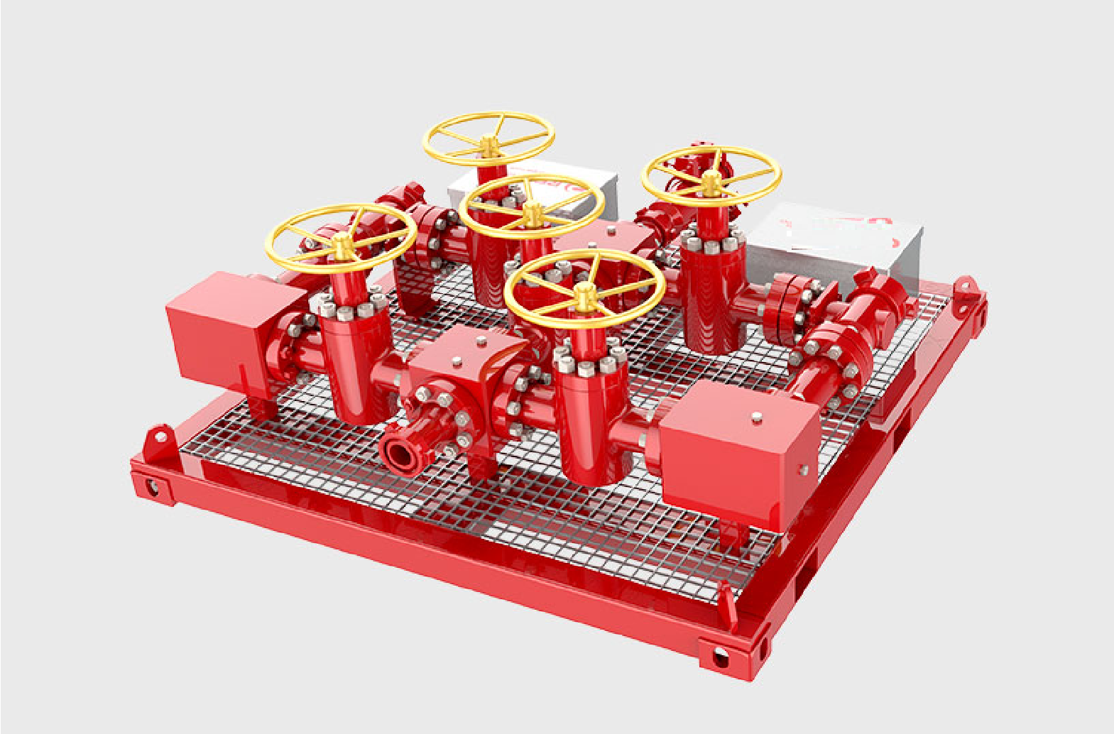
The choke manifold is used to reduce well pressure and control the flow rate before the flow enters the processing equipment. Choke manifolds are component designs consisting of four, five or eight manual valves. Positioned on one side of the flow path an adjustable choke allows variable flow control for flexibility during clean-up rates. On the other side a fixed orifice allows a more accurate flow control for predetermined flow rates. The choke allows the operator to control the well flow by enabling progressive manual, powered, or fixed control of the well stream by opening, closing, or selecting a fixed orifice. A number of choke manifold configurations and sizes are available for different pressures and temperatures to meet the client’s demands and well conditions. Both single and dual isolation valve arrangements can be supplied.
Applications
- Onshore and offshore oil and gas well testing, and clean up operations
- Flow back after stimulation operations and workovers HPHT
Technical Specifications:
- Size , Nominal Diameter (inch ) : 3’’, 4’’ 6’’
- Working Pressure (psi) : 5000, 10000 , 15000
- Design Code and Material Compliance : API 6A , NACE MR-0175

